How To Size A Liquid Control Valve
Sizing a control valve means selecting a valve with the correct size orifice to allow good control of flow rate within a required range.
There are other important factors to consider when selecting a control valve, such as valve type and valve characteristic but this article will concentrate on valve sizing.
Sizing a control valve for a particular duty is governed by the required flow rate the valve must pass and the pressure drop that can be allowed across the valve.
Steps To Accurately Size A Liquid Control Valve
- Specify the required design flow rate
- Specify the allowable pressure drop across the valve
- Choose a valve type and body size from the manufacturers' tables
- Calculate the first estimate of the piping geometry factor
- Determine if the flow through the valve will be sub-critical or critical. That is, will some of the liquid vaporise causing flashing or cavitation?
- Calculate the effective pressure drop across the valve
- Calculate the first estimate of the required valve Cv
- Check that the calculated Cv is less than the actual Cv of the selected valve (re-select suitable valve from manufacturers' tables if required)
- Check that valve control range is OK
- If the Cv and control range are suitable the valve is correctly sized. If not re-select another valve and repeat the sizing procedure from Step 3
Sizing a control valve accurately is an iterative process requiring manufacturer's information and knowledge of the piping system in which the valve is to be installed.
However, the procedure is fairly simple and straightforward. It becomes even easier if it is known that the liquid will not flash or cavitate as it flows through the valve. For preliminary estimates of control valve size it is usually OK to assume that the piping geometry factor is 1.
Calculate Control Valve Cv
Traditionally, control valves are sized using a special form of the orifice equation which gives the valve orifice size as a "valve flow coefficient" or Cv.
The Cv is defined as the flow rate of water in US gallons per minute that can pass through a valve with a pressure drop of 1 psi at a temperature of 60F.
The equation for calculating the Cv in US units is:
$$ Cv = {\frac {Q}{F_p} \sqrt \frac {SG}{\Delta P_{eff}}} $$
Where:
$Cv =$ valve flow coefficient
$Q =$ volumetric flow rate (USgpm)
$F_p =$ piping geometry factor
$SG =$ specific gravity of liquid relative to water
$\Delta_{eff} =$ effective pressure drop across valve (psi)
Effective Pressure Drop
The effective pressure drop across a liquid control valve depends on the nature of the liquid flowing through the valve and the valve design.
If the pressures upstream, inside and downstream of the control valve are greater than the vapour pressure of the liquid at the flowing temperature, the effective pressure drop is equal to the actual pressure difference between the upstream and downstream sides of the valve. In this case, the flow is said to be "sub-critical" and the fluid remains in the liquid phase throughout the system.
In the vast majority of cases it is preferable to maintain sub-critical flow as it reduces valve damage, improves controllability and requires simpler, less expensive valve designs.
However, if the liquid vapour pressure exceeds the system pressure inside or downstream of the valve, vaporisation will occur and the flow will become "critical". In this case, the effective pressure drop across the valve will be limited by the valve design and the physical properties of the liquid. When the flow is "critical", the pressure downstream of the valve does not affect the flow rate.
The flow is sub-critical if:
$$ P_1 - P_2 < \Delta P_{max} $$
For sub-critical flow:
$$ \Delta P_{eff} = P_1 - P_2 $$
Where:
$$ \Delta P_{max} = F^2_L (P_1 -F_vP_v) $$
$$ F_F = 0.96 - 0.28 \sqrt \frac{P_v}{Pc} $$
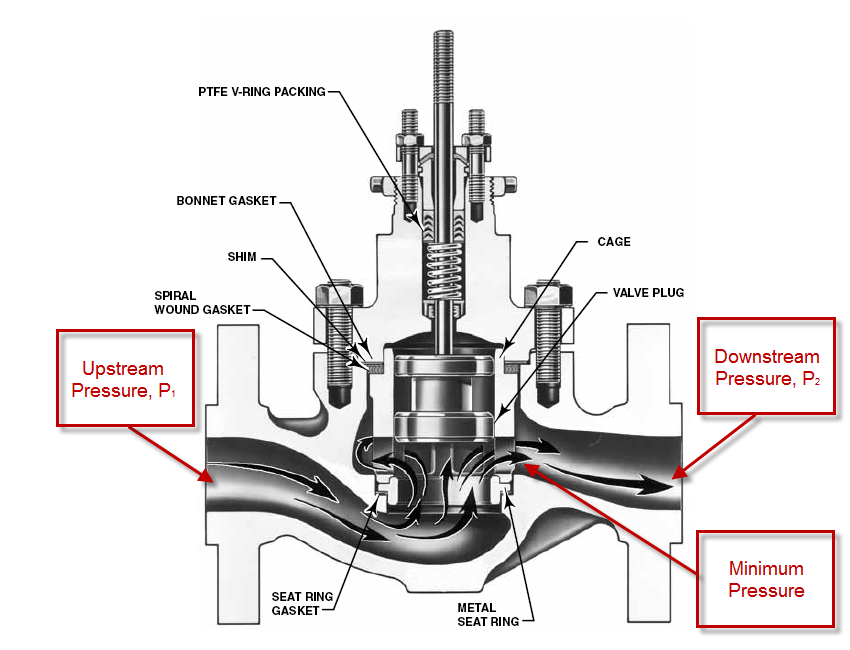
$ P_1 =$ pressure upstream of valve
$ P_2 =$ pressure downstream of valve
$ \Delta_{max} =$ maximum effective pressure drop across valve
$ F_L =$ valve liquid pressure recovery factor
$ F_F =$ liquid critical pressure ratio factor
$ P_v =$ liquid vapour pressure at flowing temperature
$ P_c =$ liquid critical pressure
For critical flow:
$$ \Delta P_{eff} = \Delta P_{max} $$
Valve Liquid Pressure Recovery Factor, FL
The valve liquid pressure recovery factor is the ratio of effective pressure drop to the pressure difference between the upstream pressure and the vena contracta pressure.
The valve liquid pressure recovery factor is usually measured experimentally and is tabulated in valve manufacturers' catalogues.
Liquid Critical Pressure Ratio Factor, FF
The liquid critical pressure ratio factor is a means of estimating the pressure at the vena contracta of the valve under critical flow conditions.
Piping Geometry Factor, Fp
The piping geometry factor is an allowance for the pressure drop associated with fittings that may be connected directly upstream and/or downstream of the valve.
If no fittings are connected to the valve, the piping geometry factor is 1.
The piping geometry factor is often listed in valve manufacturers catalogues. Alternatively, it can be calculated using:
$$ F_p = \left[ 1 + \frac {\Sigma K}{890} \left(\frac {Cv}{d^2_{valve}} \right) \right] $$
Where:
$ \Sigma K =$ sum of fittings factors
$ d_{valve} =$ control valve body nominal size (inches)
$Cv =$ Cv of selected control valve
Most commonly, the fittings connected to a control valve are upstream and downstream reducers. In this case the sum of the fittings factors for the reducers is:
$$ \Sigma K = 1.5 \left( 1 - \frac{d^2_{valve}}{d^2_{pipe}} \right)^2 $$
$ d_{pipe} =$ piping nominal diameter (inches)
Note:
Determining the control valve Cv becomes an iterative process when the piping geometry factor doesn't equal 1.
- Estimate the required Cv
- Select an appropriate valve from the manufacturers' tables
- Calculate Fp using the actual Cv of the selected valve
- Re-calculate the required Cv using the value of Fp determined in Step 3
- Check that the re-calculated Cv is less than the actual Cv of the selected valve
- If the re-calculated Cv is less than the actual Cv, the selected valve is adequately sized
- If the re-calculated Cv is greater than the actual Cv of the selected valve, select another valve with a larger Cv and return to Step 3
Control Valve Sizing Rules Of Thumb
There are many rules of thumb designed to help with control valve sizing. The following guidance is taken from "Rules of Thumb For Chemical Engineers" by Carl Brannan and the author's personal notes.
- Set the design flow as the greater of:
- 1.3 x normal flow rate
- 1.1 x maximum required flow rate
- Set the control pressure drop to equal 50% - 60% of the frictional pressure loss of the piping system
- Limit the maximum flow rate : minimum flow rate turndown to 5:1 for linear trim valves and 10:1 for equal percentage trim valves
- The valve should be able to control the required range of flow rates between 10% and 80% of valve opening
- Ideally select a valve that has a body size 1 pipe size smaller than the pipe in which it is to be installed (e.g. select a 3" valve for a 4" pipe)
- Never select a valve larger than the pipe in which it is to be installed
How To Size A Liquid Control Valve Example
The following example has been adapted from the Emerson Control Valve Handbook.
We need to size a valve in liquid propane duty. The required information is given below:
- Design flow rate = 800 US gpm
- Upstream pressure = 314.7 psia
- Downstream pressure = 289.7 psia
- Pressure drop across valve = 25 psi
- Liquid temperature = 70F
- Propane specific gravity = 0.5
- Propane vapour pressure = 124.3 psia
- Propane critical pressure = 616.3 psia
- Pipe size = 4 inch
Calculation
Following the steps given at the start of this article:
- Design flow rate = 800 US gpm
- Allowable pressure drop across the valve = 25 psi
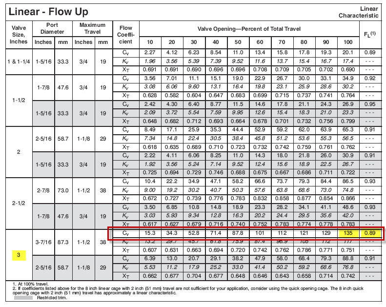
- We will choose an Emerson 3" ES globe valve with linear trim as the preliminary selection. From the valve table we can see that the actual Cv is 135 and FL is 0.89
- We will assume that 4" x 3" reducers will be used to install the selected 3" valve in the 4" pipe. In this case the piping geometry factor is: ΣK = 1.5 (1 – (32 / 42))2 = 0.287 FP = [1 + (0.287 / 890)(135 / 32)2]-0.5 = 0.96
- Check if flow through the valve is sub-critical or critical: FF = 0.96 – 0.28 (124.3 / 616.3) = 0.83 DPmax = (0.89)2 (314.7 – 0.83 x 124.3) = 167.6 psi P1 – P2 = 314.7 – 289.7 = 25 psi Therefore: P1 – P2 < DPmax so the flow is sub-critical
- The effective pressure drop across the valve is P1 – P2 because the flow is sub-critical DPeff =25 psi
- Calculate the first estimate of Cv: Cv = (800 / 0.96)(0.5 / 25)0.5 = 117.9
- The calculated required Cv of 117.9 is less than the actual Cv of the selected valve of 135 so the valve is large enough
- Check if the control valve range is OK: From the valve table, the selected valve will be about 75% open to give the required Cv of 117.9. This is within the acceptable control range of 10% to 80% of valve opening.
- The selected 3" linear trim valve is correctly sized for the specified duty
Result
The selected valve is an Emerson 3" ES globe valve with linear trim and a maximum Cv of 135.
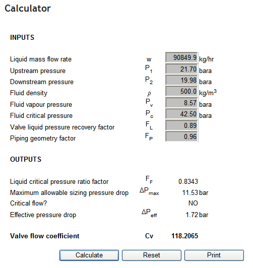
Blackmonk Engineering Calculator Result
The output from the Blackmonk Engineering Liquid Control Valve Calculator is attached below for comparison. The values used in the example have been converted to metric units. As you can see the calculated Cv is virtually identical to the hand calculation (118.2 compared to 117.9).