Sizing a control valve means selecting a valve with the correct size orifice to allow good control of flow rate within a required range.
There are other important factors to consider when selecting a control valve, such as valve type and valve characteristic but this article will concentrate on valve sizing.
The procedure explained in this article applies to gas and vapour control valves including steam control valves. The method for sizing gas control valves is based on the method for sizing liquid control valves. More information on sizing a liquid control valve can be found here: “How To Size A Liquid Control Valve”.
Sizing a control valve for a particular duty is governed by the required flow rate the valve must pass and the pressure drop that can be allowed across the valve.
Steps To Accurately Size A Gas Control Valve
- Specify the required design flow rate
- Specify the allowable pressure drop across the valve
- Choose a valve type and body size from the manufacturers’ tables
- Calculate the first estimate of the piping geometry factor and pressure drop ratio factor
- Determine if the flow through the valve will be sub-critical or critical
- Calculate the effective pressure drop ratio across the valve
- Calculate the expansion factor
- Calculate the first estimate of the required valve Cv
- Check that the calculated Cv is less than the actual Cv of the selected valve (re-select suitable valve from manufacturers’ tables if required)
- Check that valve control range is OK
- If the Cv and control range are suitable the valve is correctly sized. If not re-select another valve and repeat the sizing procedure from Step 3 Sizing a control valve accurately is an iterative process requiring manufacturer’s information and knowledge of the piping system in which the valve is to be installed.
The procedure is a little bit more complicated than sizing a liquid control valve but is certainly not difficult. For preliminary estimates of control valve size it is usually OK to assume that the piping geometry factor is 1.
Calculate Control Valve Cv
Gas control valves are sized using a modified version of the liquid control valve equation. As for liquid control valves, the valve orifice size as given as a “valve flow coefficient” or Cv.
The Cv is defined as the flow rate of water in US gallons per minute that can pass through a valve with a pressure drop of 1 psi at a temperature of 60F.
The equation for calculating the Cv for a gas control valve using metric units is:
Where:
\(Cv =\) valve flow coefficient
\(w =\) mass flow rate (kg/h)
\(F_p =\) piping geometry factor
\(Y =\) expansion factor
\(P_1 =\) upstream pressure (bara)
\(ρ_1 =\) gas density at upstream conditions (kg/m3)
Effective Pressure Drop
The effective pressure drop across a gas control valve depends on the properties of the gas flowing through the valve and the valve design.
If the pressure downstream of the valve is lower than a critical value, the flow through the valve will be choked. Choked flow is also known as critical flow.
The flow is sub-critical if:
For sub-critical flow:
For critical flow:
Where:
\(F_k =\) ratio of specific heats factor
\(k =\) ratio os specific heat capacities of gas flowing through valves
\(X_T =\) pressure drop ratio factor
Pressure Drop Ratio Factor, XT
The pressure drop ratio factor is the pressure drop ratio required to produce critical flow through the valve when Fk is equal to 1.
The valve pressure drop ratio is measured experimentally and is tabulated in valve manufacturers catalogues.
If the valve has fittings connected directly upstream and/or downstream, the pressure drop ratio factor must be modified to account for expansion and contraction of the fluid through the fittings.
The modified pressure drop ratio factor, XTP is calculated using:
Where:
\(K_i =\) inlet fittings head loss coefficients
\(K_1 =\) resistant coefficient of upstream fittings
\(K_{B1} =\) inlet Bernoulli coeffient = \(1 - \left( {\frac {d_{valve}}{d_{pipe}}} \right)^4\)
\(d_{valve} =\) control valve body nominal size (inches)
For valves installed with a reducer installed upstream, the inlet fittings head loss coefficient becomes:
Expansion Factor, Y
The expansion factor accounts for the expansion of gas flowing through the valve as the pressure reduces from inlet to outlet. The expansion factor is the ratio of flow coefficients for a gas to that for a liquid at the same Reynolds number.
The expansion factor must be less than or equal to a value of 0.667. The following equation defines the expansion factor:
Piping Geometry Factor, Fp
The piping geometry factor is an allowance for the pressure drop associated with fittings that may be connected directly upstream and/or downstream of the valve.
If no fittings are connected to the valve, the piping geometry factor is 1.
The piping geometry factor is often listed in valve manufacturers catalogues. Alternatively, it can be calculated using:
\(\sum K =\) sum of fittings factors
\(d_{valve} =\) control valve body nominal size (inches)
\(Cv =\) Cv of selected control valve
Most commonly, the fittings connected to a control valve are upstream and downstream reducers. In this case the sum of the fittings factors for the reducers is:
\(d_{pipe} =\) piping nominal diameter (inches)
Note:
Determining the control valve Cv becomes an iterative process when the piping geometry factor doesn’t equal 1.
- Estimate the required Cv
- Select an appropriate valve from the manufacturers’ tables
- Calculate Fp and XTP using the actual Cv of the selected valve
- Re-calculate the required Cv using the values of Fp and XTP determined in Step 3
- Check that the re-calculated Cv is less than the actual Cv of the selected valve
- If the re-calculated Cv is less than the actual Cv, the selected valve is adequately sized
- If the re-calculated Cv is greater than the actual Cv of the selected valve, select another valve with a larger Cv and return to Step 3
Control Valve Sizing Rules Of Thumb
There are many rules of thumb designed to help with control valve sizing. The following guidance is taken from “Rules of Thumb For Chemical Engineers” by Carl Brannan and the author’s personal notes.
- Set the design flow as the greater of:
- 1.3 x normal flow rate
- 1.1 x maximum required flow rate
- Set the control pressure drop to equal 50% - 60% of the frictional pressure loss of the piping system
- Limit the maximum flow rate : minimum flow rate turndown to 5:1 for linear trim valves and 10:1 for equal percentage trim valves
- The valve should be able to control the required range of flow rates between 10% and 80% of valve opening
- Ideally select a valve that has a body size 1 pipe size smaller than the pipe in which it is to be installed (e.g. select a 3” valve for a 4” pipe)
- Never select a valve larger than the pipe in which it is to be installed
How To Size A Gas Control Valve Example
The following example has been adapted from the Emerson Control Valve Handbook.
We need to size a valve in steam duty. The required information is given below:
Design flow rate = 125000 lb/hr = 56689 kg/hr
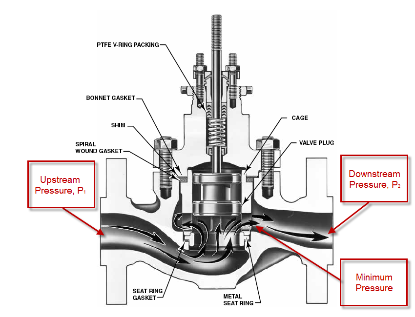
Upstream pressure = 500 psig = 35.50 bara
Downstream pressure = 250 psig = 18.26 bara
Pressure drop across valve = 250 psi = 17.24 bar
Upstream steam temperature = 500F
Density of steam at upstream conditions = 1.0434 lb/ft3 = 16.71 kg/m3
Steam ratio of specific heat capacities = 1.28
Pipe size = 6 inch
Calculation
Following the steps given at the start of this article:
- Design flow rate = 56689 kg/hr
- Allowable pressure drop across the valve = 17.24 bar
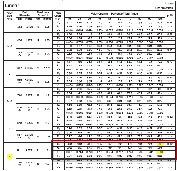
- We will choose an Emerson 4” ED globe valve with linear cage as the preliminary selection. From the valve table we can see that the actual Cv is 236 and XTP is 0.688
- We will assume that 6” x 4” reducers will be used to install the selected 4” valve in the 6” pipe. In this case the piping geometry factor is:
ΣK = 1.5 (1 – (42 / 62))2 = 0.463
FP = [1 + (0.463 / 890)(236 / 42)2]-0.5 = 0.95
The pressure drop ratio factor, XT = 0.688
The inlet fittings head loss coefficient is:
Ki = 0.5 (1 – (42 / 62))2 + 1 - (4 / 6)4 = 0.957
So the modified pressure drop ratio factor is:
XTP = 0.688 / 0.952[1 + 0.688 x 0.957 / 1000 (236 / 42)2]-1 = 0.667 - Check if flow through the valve is sub-critical or critical:
Fk = 1.28 / 1.4 = 0.91
Fk XTP = 0.91 x 0.667 = 0.607
(P1 – P2) / P1 = (35.50 – 18.26) / 35.50 = 0.486
Therefore: (P1 – P2) / P1 < Fk XTP so the flow is sub-critical - The effective pressure drop ratio across the valve is (P1 – P2) / P1 because the flow is sub-critical:
Xeff = 0.486 - Calculate the expansion factor:
Y = 1 – 0.486 / (3 x 0.91 x 0.667) = 0.733 - Calculate the first estimate of Cv:
Cv = 56689 / (27.3 x 0.95 x 0.733 (0.486 x 35.50 x 16.71)0.5) = 175.6 - The calculated required Cv of 175.6 is less than the actual Cv of the selected valve of 236 so the valve is large enough
- Check if the control valve range is OK:
From the valve table, the selected valve will be a just less 70% open to give the required Cv of 175.6. This is within the acceptable control range of 10% to 80% of valve opening. - The selected 4” linear cage valve is correctly sized for the specified duty
Result
The selected valve is an Emerson 4” ED globe valve with linear trim and a maximum Cv of 236.
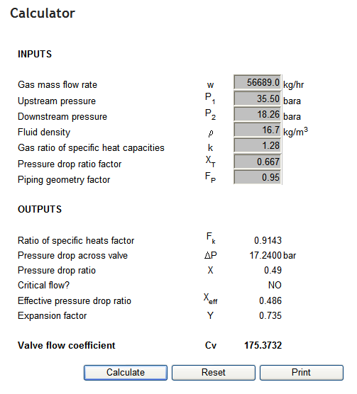
Blackmonk Engineering Calculator Result
The output from the Blackmonk Engineering Liquid Control Valve Calculator is attached below for comparison. As you can see the calculated Cv is virtually identical to the hand calculation (175.4 compared to 175.6).